Home Automation Kubernetes Cluster – Part 2: Installing Talos Linux
This is part 2 of my Kubernetes Home Automation Cluster series. In the first part, we talked about how to assemble the hardware. In this part, we’ll go over how to get Kubernetes up and running.
Why Talos Linux?
As I said in Part 1, I really liked the Talos Linux project when I started searching for the best way to run Kubernetes on an SBC. I did a proof of concept on several different hardware/software combinations during my search for the best edge Kubernetes clusters for my home automation needs but ultimately settled on Talos. I won’t go into all my POCs right now because this article is going to be long enough already. I tried both purpose-built Kubernetes distributions and Kubernetes on standard Linux, but Talos stood out as the best fit for my needs.
Prerequisites
Before we begin, here’s what you’ll need:
- A Rock 4 SE SBC or compatible hardware
- An SD card (at least 16 GB)
- A computer with an SD card reader
- Ethernet cable and access to your network’s DHCP server
- A tool to flash disk images (I use Balena Etcher)
Downloading and Flashing the Talos Image
Let’s get started by visiting the Talos Image Factory:
- Select the "Single Board Computer" option.
- Choose the version of Talos you want to install. The current version, as of the time of writing, is 1.9.1.
- Next, select your SBC board. In our case, that’s the Rock 4 SE.
- Click "Next" on the System Extension and Kernel Arguments screens until you reach the download page.
Download the disk image file from the "Disk Image" link. Then, flash it to your SD card using your favorite image flashing tool. I personally like Balena Etcher because it makes flashing an image to an SD card easy.
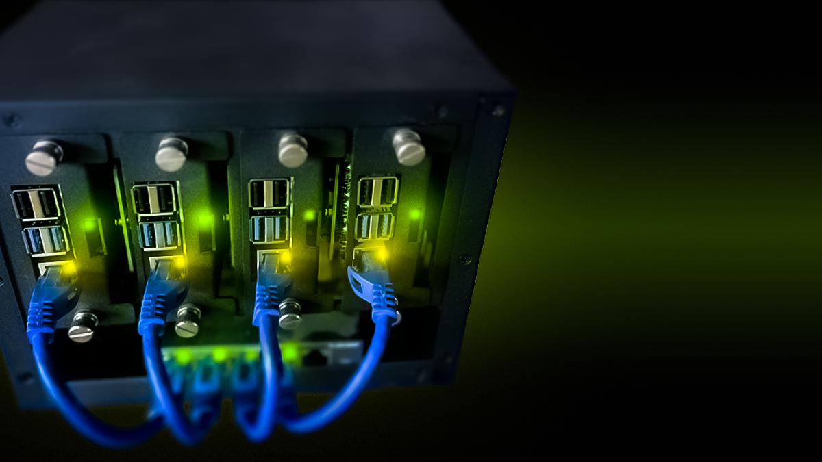
Booting the Board
Once you’ve flashed the SD card with the Talos image, insert it into your Rock 4 SE. Plug in the Ethernet cable and power up the board. You should see the board’s lights come on, indicating activity.
Finding Your Device’s IP Address
Next, we need to find the IP address assigned to the board by your network’s DHCP server. How you do this depends on your router or network setup:
- Using Your Router: Log in to your router’s admin interface and look for connected devices.
- Using Network Tools: Tools like
nmapor Angry IP Scanner can help you find the new device. - Omada Users: I use TP-Link Omada networking and can see the device’s IP address in the interface.
Once you’ve located the IP, you can confirm it’s your Talos system by running the following command:
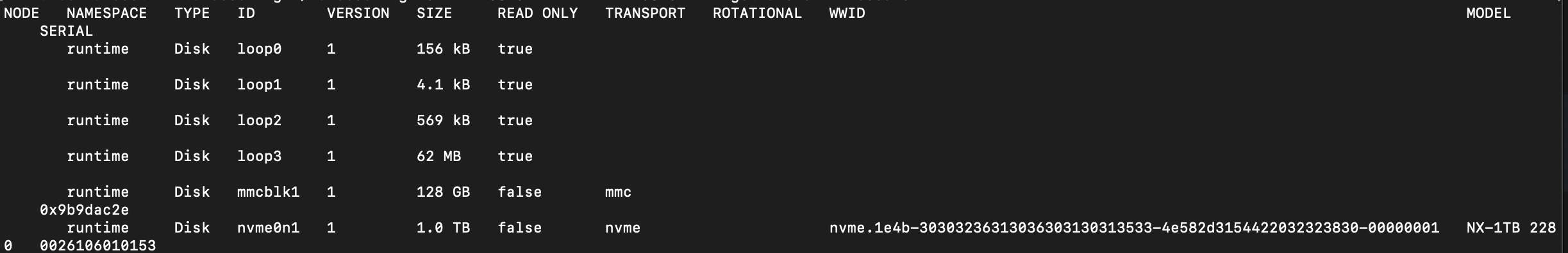
talosctl -e <IP_ADDRESS> -n <IP_ADDRESS> get disks --insecureThis command should list all the disks on the machine. You can also confirm your NVMe drive is detected. You should see something like this:
Configuring Talos
At this point, Talos is booted in maintenance mode and isn’t fully operational yet. The next step is to apply a configuration file to the node so it can boot into the appropriate role. We’re essentially following the Talos Getting Started guide.
Choosing the Cluster Endpoint
The cluster-endpoint is the IP address for your Talos API server. In an all-metal setup like this, you need a stable IP for the control plane node. Talos uses a VIP (Virtual IP) to manage this. A VIP is just an unassigned IP address on your network, and Talos ensures it’s always assigned to the active control plane node using etcd.
Then, run this command:
talosctl gen config <cluster-name> <cluster-endpoint>Editing the Control Plane File
The gen config command generates several files with very good defaults. The one we’re currently concerned with is the control-plane.yaml file. We need to edit this file to configure our bare-metal cluster. Below are the changes we need to make:
Network Changes
We need to update the network configuration to ensure the node is set up correctly for the cluster. Refer to the Talos documentation for more details, but here are the sections to focus on: DeviceSelector, DHCP, and VIP.
Here’s an example of the network portion:
network:
  interfaces:
    - deviceSelector:
        driver: rk*
      dhcp: true
      vip:
        ip: 192.168.0.45 # Specifies the IP address to be used.
  nameservers:
    - 8.8.8.8
    - 1.1.1.1
Setting the Installation Disk
To ensure the OS installs on the correct media, we’ll use a diskSelector instead of specifying the disk by name. This makes the setup resilient to changes in disk naming conventions:
install:
  image: ghcr.io/siderolabs/installer:v1.9.0 # The image used for installation.
  wipe: false # Indicates if the installation disk should be wiped.
  diskSelector:
    type: sd
Mounting the NVMe Drive
Next, we’ll configure the NVMe drive to mount at a usable location. Update the disks section of the file:
disks:
  - device: /dev/nvme0n1 # The name of the disk to use.
    partitions:
      - mountpoint: /var/mnt/extra # Where to mount the partition.
This configuration ensures the NVMe drive is mounted at /var/mnt/extra.
Allowing Workloads on Control Plane Nodes
Finally, enable workloads to run on control-plane nodes by updating this setting:
allowSchedulingOnControlPlanes: trueWith these changes, your control-plane file is ready to bootstrap your bare-metal cluster.
Control Plane Node Setup
The following steps are adapted from the Talos Getting Started guide:
Configuring the First Control Plane Node
First, we need to apply the configuration to our control plane node using the talosctl apply-config command. Replace <IP_ADDRESS> with the IP address of your node:
talosctl apply-config -e <IP_ADDRESS> -n <IP_ADDRESS> --talosconfig ./talosconfig --file controlplane.yaml --insecureThis step applies the settings from your controlplane.yaml file, including network, disk, and scheduling configurations, ensuring the node is properly set up to join the cluster.
Bootstrapping the Control Plane Node
Next, bootstrap the first node of the control plane cluster. This step sets up the etcd cluster and starts the Kubernetes control plane components:
talosctl bootstrap -e <IP_ADDRESS> -n <IP_ADDRESS> --talosconfig ./talosconfigVerifying the Node
After a few moments, you should be able to download the Kubernetes client configuration and start using your cluster:
talosctl kubeconfig --nodes <IP_ADDRESS> --endpoints <IP_ADDRESS> --talosconfig=./talosconfigThis command merges the cluster configuration into your default Kubernetes configuration file. If you’d like to save it to a different file, you can specify an alternative filename:
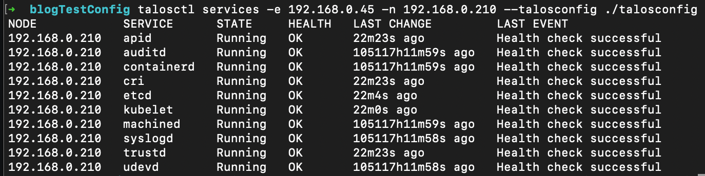
talosctl kubeconfig alternative-kubeconfig --nodes <IP_ADDRESS> --endpoints <IP_ADDRESS> --talosconfig ./talosconfigTo make sure that everything is running corrctly, I like to issue the services command via talosctl like:
talosctl services -e <VIP_IP_ADDRESS> -n <NODE_IP_ADDRESS> --talosconfig ./talosconfigYou should get something like this:
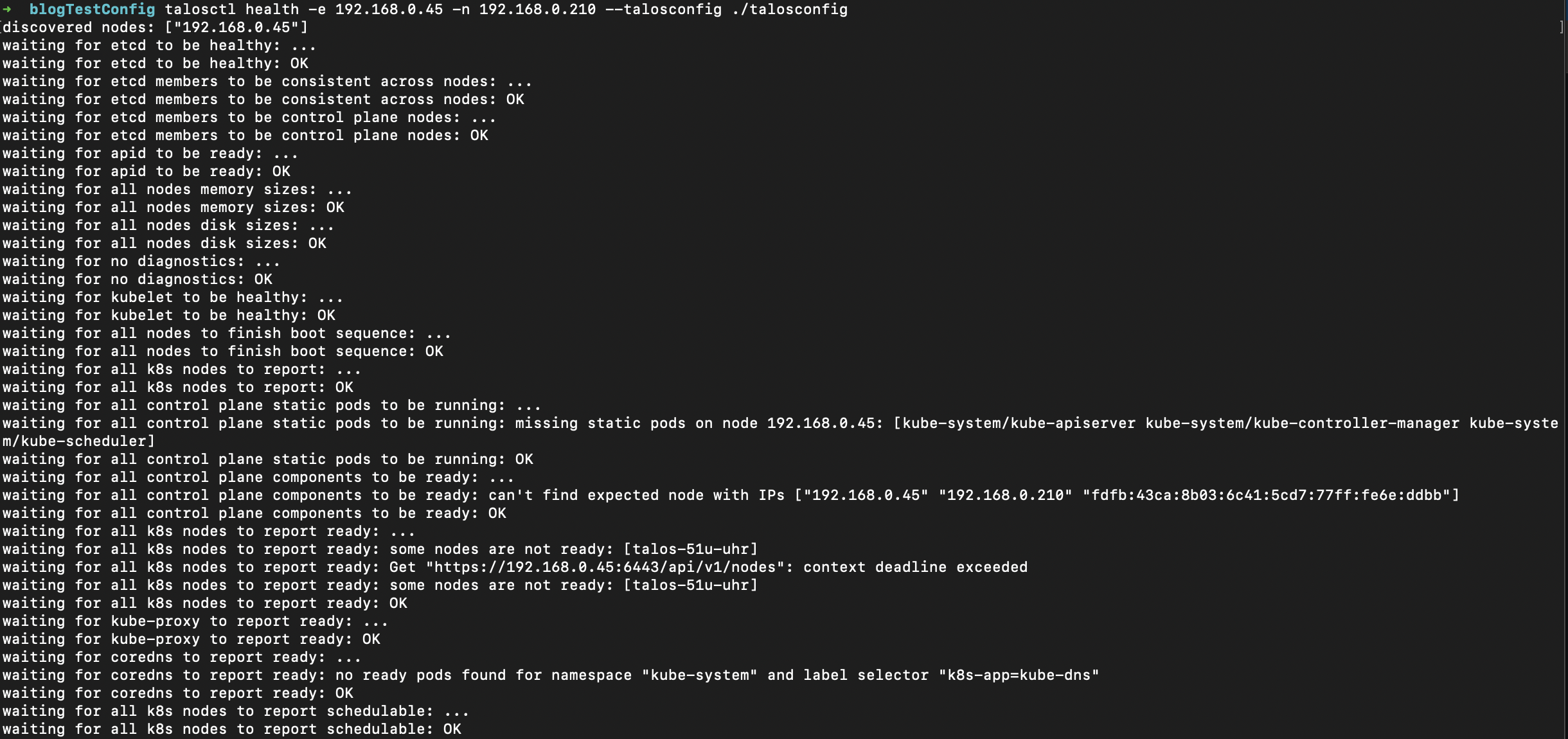
You can also run the "health" command like:
talosctl health -e <VIP_IP_ADDRESS> -n <NODE_IP_ADDRESS> --talosconfig ./talosconfigYou should get something like this:
Now, you can connect to your Kubernetes cluster and verify that your nodes are up and running:
kubectl get nodesYou should see your control plane node listed and ready.
Adding Additional Nodes
Adding the remaining SBC boards to your cluster is as simple as scaling up. Ideally, you’ll want at least three control plane nodes for redundancy. To scale your cluster, simply apply your controlplane.yaml file to two additional nodes:
talosctl apply-config -e <VIP_IP_ADDRESS> -n <NODE_IP_ADDRESS> --talosconfig ./talosconfig --file controlplane.yaml --insecureAgain, a good way to check node health is to run the "talosctl services" command:
talosctl services -e <VIP_IP_ADDRESS> -n <NODE_IP_ADDRESS> --talosconfig ./talosconfigYou should get something that looks like this:
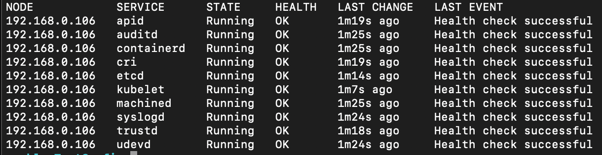
If you get something that looks like this:
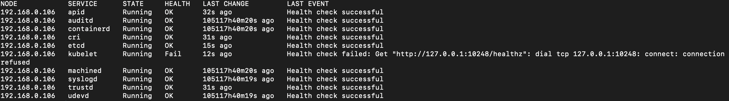
If issues persist, rebooting the node typically resolves them and allows provisioning to complete.
You can do this with the following command:
talosctl reboot -e <NODE_IP_ADDRESS> -n <NODE_IP_ADDRESS> --talosconfig ./talosconfig Once you have configured the additional nodes, you can verify their status by running the following command:
kubectl get nodesAdding Additional Worker Nodes
If you have more than three nodes to add to your cluster, you can make similar edits to the worker.yaml file as you did to the controlplane.yaml file. There are a few exceptions to note:
- You do not need to set the
VIPin the worker configuration file. - You also do not need to set the
allowSchedulingOnControlPlanesproperty.
Conclusion
I had originally planned for this to be a two-article series, but after writing this, I feel this is a good stopping point. If you’re already familiar with Kubernetes, you can stop here. However, if you’re looking for a "batteries included" version of Kubernetes, I encourage you to check out my next article. There, I’ll explain how to set up an application manager, a load balancer, and an ingress controller.